
GRE Tunnel Tutorial
GRE stands for Generic Routing Encapsulation, which is a very simple form of tunneling. With GRE we can easily create a virtual link between routers and allow them to be directly connected, even if they physically aren’t. Let’s have a look at the topology below:
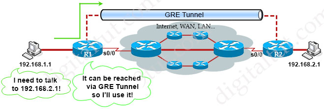
Suppose R1 and R2 are routers at two far ends of our company. They are connected to two computers who want to communicate. Although R1 and R2 are not physically connected to each other but with GRE Tunnel, they appear to be! This is great when you have multiple end points and don’t care the path between them. The routing tables of two routers show that they are directly connected via GRE Tunnel.
How GRE Tunnel works
When the sending router decides to send a packet into the GRE Tunnel, it will “wrap” the whole packet into another IP packet with two headers: one is the GRE header (4 bytes) which uses to manage the tunnel itself. The other is called “Delivery header” (20 bytes) which includes the new source and destination IP addresses of two virtual interfaces of the tunnel (called tunnel interfaces). This process is called encapsulation.
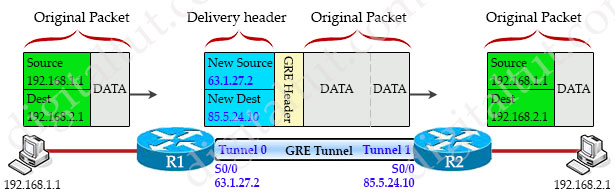
In the example above when R1 receives an IP packet, it wraps the whole packet with a GRE header and a delivery header. The delivery header includes new source IP address of 63.1.27.2 (the IP address of R1’s physical interface which is used to create tunnel) and new destination IP address of 85.5.24.10 (the IP address of R2’s physical interface which is used to create tunnel).
It is important to note that the GRE tunnel does not encrypt the packet, only encapsulate it. If we want to encrypt the packet inside GRE Tunnel we must use IPSec but it is out of CCNA scope so we will not mention here.
When the GRE packet arrives at the other end of the tunnel (R2 in this case), the receiving router R2 needs to remove the GRE header and delivery header to get the original packet.
Unlike VPN which does not support multicast, GRE tunnel does support multicast so many popular routing protocols (like OSPF, EIGRP) can operate along with.
Note: The IP addresses of the two ends of GRE Tunnel (63.1.27.2 & 85.5.24.10 in this case) can be in the same subnet or different subnet (like over the Internet with public IP addresses), provided that two routers know how to reach each other’s tunnel IP address. For example in this case R1 must know how to reach 85.5.24.10 and R2 must reach 63.1.27.2.
Now you learned the basis of GRE Tunnel. It is important to show you the related GRE configuration of the example above. Suppose OSPF is used in our company.
| R1 (GRE config only) interface s0/0/0 ip address 63.1.27.2 255.255.255.0 interface tunnel0 ip address 10.0.0.1 255.255.255.0 tunnel mode gre ip //this command can be ignored tunnel source s0/0 tunnel destination 85.5.24.10 router ospf 1 network 192.168.1.0 0.0.0.255 area 0 |
R2 (GRE config only) interface s0/0/0 ip address 85.5.24.10 255.255.255.0 interface tunnel1 ip address 10.0.0.2 255.255.255.0 tunnel source 85.5.24.10 tunnel destination 63.1.27.2 router ospf 1 network 192.168.1.0 0.0.0.255 area 0 |
In the above R1 configuration, the command interface tunnel0 create the virtual tunnel 0 interface, which is called a tunnel interface. We can use any number. The tunnel numbers do not need to match on two routers so on R2 we can use “interface tunnel1” without any problem.
The next line assigns the IP address for the tunnel interface: 10.0.0.1/24. The IP addresses of two tunnel interfaces must be in the same subnet (10.0.0.1/24 on R1 & 10.0.0.2/24 on R2 in this case).
The command tunnel mode gre ip is in fact not necessary as this is the default setting. We just want to show you this command and let you know that we are configuring a traditional point-to-point GRE. There are other GRE modes like “tunnel mode gre multipoint” used in DMVPN or “tunnel mode gre ipv6” to encapsulate IPv4 packets in an IPv6 infrastructure.
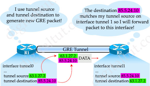
Next we have to specify the tunnel source and tunnel destination with “tunnel source …” and “tunnel destination” commands. For “tunnel source” command, we can either specify the interface or the IP address of the interface. When we define the tunnel source and tunnel destination in the tunnel interface, the router will add these IP addresses to the GRE packet generated by the tunnel interface. At the receiving end, the router looks for the tunnel destination and decapsulates the packet, then forwards it to the specific tunnel interface.
Note: We can use loopback interface as the tunnel source or destination. Traffic will flow through the best physical path toward the tunnel destination.
One last note, GRE tunnels are stateless which means the tunnel endpoint does not keep any information about the state or availability of the remote tunnel endpoint. Therefore the local tunnel endpoint does not bring the line protocol of the GRE tunnel interface down if the remote tunnel endpoint is unreachable. For example, if R2 tunnel interface is brought down for some reason, R1 tunnel interface will remain in up state.
GRE Keepalives
GRE tunnels are designed to be completely stateless. This means that each tunnel endpoint does not keep any information about the state or availability of the remote tunnel endpoint. A consequence of this is that the local tunnel endpoint router does not have the ability to bring the line protocol of the GRE Tunnel interface down if the remote end of the tunnel is unreachable. Such scenarios would cause data packets that go through the GRE tunnel to be “black holed”. Keepalives on the GRE tunnel interface are used in order to solve this issue in the same way as keepalives are used on physical interfaces. With this feature, the tunnel interface dynamically shuts down if the keepalives fail for a certain period of time.
GRE keepalive packets may be sent from both sides of a tunnel or from just one side. If they are sent from both sides, the period and retry parameters can be different at each side of the link. If you configure keepalives on only one side of the tunnel, the tunnel interface on the sending side might perceive the tunnel interface on the receiving side to be down because the sending interface is not receiving keepalives. From the receiving side of the tunnel, the link appears normal because no keepalives were enabled on the second side of the link.
Reference: https://www.cisco.com/c/en/us/support/docs/ip/generic-routing-encapsulation-gre/118370-technote-gre-00.html and https://www.cisco.com/c/en/us/td/docs/ios/12_2sb/feature/guide/sb_gretk.html
If you are interested in full config for GRE please read our GRE tunnel Lab to have detailed knowledge of how to configure GRE tunnel.
| GRE Summary: + GRE tunnels are stateless, support multicast, uses IPSec for encryption + Keepalives can be used on either end or both ends + Encapsulation with new IP headers |
Recursive Routing Error
A common error in GRE Tunnel configuration is recursive routing error with such error message:
| %TUN-5-RECURDOWN: Tunnel0 temporarily disabled due to recursive routing |
This error means we advertised the tunnel destination IP address on the tunnel interface to other side. In the example above, if we advertise the R1 tunnel IP address of 10.0.0.1 to R2 (via the OSPF command “network 10.0.0.0 0.0.0.255 area 0”, for example), the recursive routing error would occur as R1 will try to reach the tunnel destination through the tunnel itself. It is like the “chicken-and-egg” situation.


Does anyone have ENCOR dumps?